
Designing a Passive LiDAR Detector Device - Hardware
At DEF CON 32, Samy Kamkar gave a talk about laser microphones. That was the only talk I made a point to watch live that year. Kamkar never disappoints and I have fond memories of trying to use a laser pointer and photodiode to hear through windows as a kid. During that talk Kamkar mentioned noticing the LiDAR dot grid projected from the back of his phone in video from a camera without an IR filter. He briefly talked about the potential for detecting when an iPhone Pro had the camera app open before a picture was even taken, because the LiDAR is activated by the default camera app at startup.
This seemed fun, and I started trying to think of ways to do it. At first I was discouraged as fellow hackers at DEF CON suggested a small device would be unable to detect the signal. I left the idea for a long time before coming back to it. After some experiments with IR remote receivers and photodiodes, I decided I would need to come to understand my target better.
Note: This article contains graphics with flashing lights. These graphics may be avoidable with Reader View.
iPhone 15 Pro TrueDepth Dot Grid Lattice Recorded in My Closet
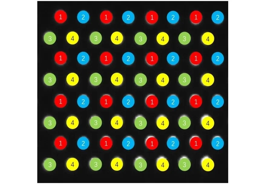
https://4sense.medium.com/apple-lidar-demystified-spad-vcsel-and-fusion-aa9c3519d4cb
iPhone TrueDepth/FaceID LiDAR systems utilize a 60hz VCSEL with a 15hz SPAD, with a duty cycle which envelopes the signal. These systems are apparent when observed through cameras without IR filters. This LiDAR system is active when an application on the device uses it, including the default camera application. As indicated in Kamkar's talk, it is possible to detect that the camera app has been opened before any image is captured.
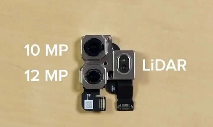
Recording of the TrueDepth LiDAR on the back of my iPhone 15 Pro
This same concept could be used to detect when an iPhone with FaceID has the screen open to the lock screen, even when unlocked or when FaceID is not enabled. Similarly, this concept could also be used to identify when there are Pixel 5 or newer devices with off-screens nearby via an infrared-based pocket detection functionality.
FaceID and Pocket Detection Sensor on my iPhone 15 Pro and Pixel 5 respectively
The TrueDepth system, present on the back of iPhone Pro models, is my primary target. Thankfully for me, between patents and existing research into this system, learning all of this information about it was a breeze! Here are some text and image excerpts from the various sources I pored over during my efforts.
“Patents such as US-20200256669 (view PDF) show that Apple uses a sparse array of single photon avalanche diodes (SPADs) to perform a kind of optical stocktake on the whereabouts of the infrared range-finding LiDAR emissions. And the iPhone maker’s True Depth Face ID design also features innovations that allows the hardware to perceive distance more accurately, albeit on different length scales.”
LiDAR on the iPhone Explained https://blog.lidarnews.com/lidar-on-the-iphone-explained/


https://4sense.medium.com/apple-lidar-demystified-spad-vcsel-and-fusion-aa9c3519d4cb
“The apparatus according to claim 1, wherein the radiation source comprises at least one vertical-cavity surface-emitting laser (VCSEL). The apparatus according to claim 2, wherein the at least one VCSEL comprises an array of VCSELs. The apparatus according to claim 1, wherein the sensing elements comprise single-photon avalanche diodes (SPADs).”
US20200256669A1 https://patents.google.com/patent/US20200256669A1/en
“The emitter has 16 stacks of 4 vertical cavity surface emitting laser (VCSEL) cells, for 64 in total. The 64 laser pulses are multiplied by a 3 × 3 diffraction optical element (DOE) to make up 576 pulses [6]. The 576 laser pulses rebounded from object surfaces are detected and the individual time elapses are measured by a single-photon avalanche diode (SPAD) image sensor. [...] It was determined that the optimal phone-to-target distance range is between 0.30 m and 2.00 m. Despite an indicated sampling frequency equal to the 60 Hz framerate of the RGB camera, the LiDAR depth map sampling rate is actually 15 Hz, limiting the utility of this sensor for vibration measurement and presenting challenges if the depth map time series is not downsampled to 15 Hz before further processing.”
Characterization of the iPhone LiDAR[…] https://pmc.ncbi.nlm.nih.gov/articles/PMC10537187/pdf/sensors-23-07832.pdf
So we know it is a 60hz, 940nm infrared signal. We also know that it can be expected to present as a rotating pattern of lattice grid beams of light. Armed with this information, I began brainstorming different approaches to measuring such a signal in a meaningful way. It was at this point that I realized I actually don't really know how to do that, so I looked it up.
LiDAR is a Flashy Light, How Do We Measure a Flashy Light
After a lot of web searching, reading other researchers' existing work, reading a lot of Wikipedia pages, struggling to get good suggestions out of LLMs, and poring over datasheets, I reached a point where I felt I was beginning to understand the objectives well enough.
See a signal as light spread into beams over an area
Sense and convert that light to an analog signal
Convert the signal from analog to digital
Measure it
The iPhone TrueDepth uses a 60hz, 940nm VCSEL DotGrid Lattice LiDAR system. In order to detect this and distinguish it from other signal sources, a device would need to sense IR signals from multiple discrete sources at high speed from which several factors could be measured. Once these factors are measured, the device would need to be able to quickly perform calculations on the measurements and programmatically decide whether the measured signals are the desired target, or noise. The factors we would want to measure are signal frequency, pulse repetition frequency, whether the signal is steady or in bursts, and how many sensors detect the same signal at the same time or not.
Now, armed with even more information I set about looking up what components might suit the needs of the project.
Hardware
This device needs to detect 940nm infrared signals. I tested several ways to accomplish this, including LEDs wired as photodiodes with and without 940nm bandpass filters, pin silicon photodiodes with and without bandpass filters, and 940nm peak pin silicon photodiodes. While LEDs wired as photodiodes were surprisingly effective, the cleanest and clearest signals were obtained using 940nm peak photodiodes.
In addition to just detecting 940nm infrared signals, the device needs to be able to discern a signal's apparent frequency. We know that the iPhone LiDAR is flashing at 60hz, so we need to be able to detect a 60hz signal, and probably harmonics of that same frequency up to some reasonable amount. This aspect of the target is where either having a 940nm peak photodiode, or using a bandpass filter really comes in handy. Most displays around you are going to be at 30, 60, or 120hz and in my testing I found that without filtering for the desired wavelength almost any display would trigger a false positive.
In order to process this signal, we need to perform operations at a high speed. Solutions for the sensors, like pin silicon photodiodes and fast components like 10mhz op-amps or schmitt triggers, work just fine for capturing these signals and making them available. To process them the device needs to strike a fair compromise between energy consumption and processing power. These days, there are countless tiny little chips that fit this bill. Since I already had development boards laying around, I chose the SAMD21 for its 48mhz processor and tiny energy footprint. Using this chip as the platform to build on, I went through several iterations of hardware designs.
IR LED-as-photodiode, no filter, raw ADC or internal comparators
Initially I attempted reading the analog signals off the diodes as ADC directly on the SAMD21 pins, which did not work well at all. Re-configuring the device to apply internal comparators to those pins, while better, also did not work well enough. After these attempts, I began looking up how to more reliably measure signals from diodes, which lead to considering Schmitt Triggers and TIA Op-Amps as options.
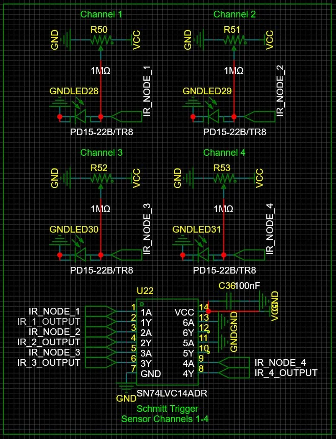
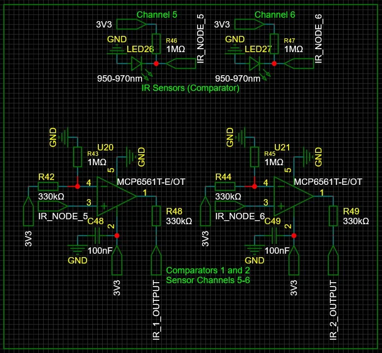
IR LED-as-photodiode, 940nm bandpass filter, Schmitt Trigger to Digital Input
A Schmitt Trigger is a sort of comparator that takes two reference inputs and performs a hysteresis wherein the two references are used as upper and lower thresholds. The output is only asserted when the input crosses the upper bounds, and only de-asserted when it crosses the lower bounds. This built-in hysteresis provides a very helpful function a regular comparator does not, though it is not as easily tuned. Schmitt Triggers, such as the 74HC14, can react to signals in something like 10ns, which translates to a speed of roughly 50mhz! This is far more than enough to process a signal at 60hz.
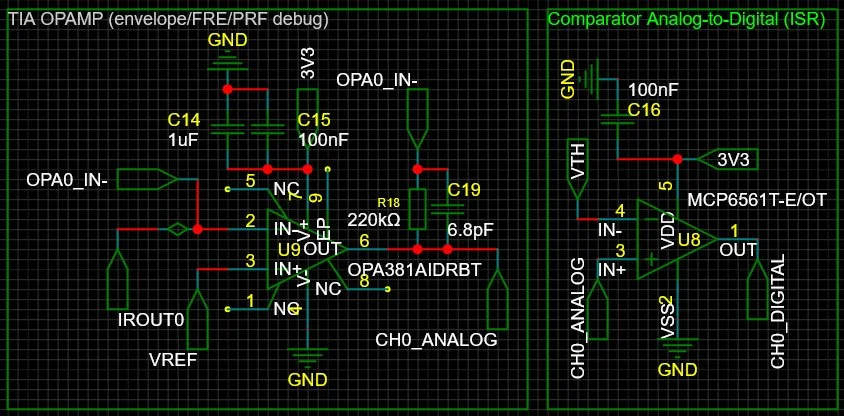
OPA381 + MCP6022 + Tuned VREF and VTH
This version implemented an MCP6002 to provide a stable reference voltage for the OPA381 Op-Amps and MCP6022 comparators. The design also implements a voltage divider and variable resistor to provide direct tuneability of the threshold voltage.
This design comes with the cost of lower processing speed, added complexity, and increased BOM. The OPA381 is still fast, like 200mhz fast, and the MCP6022 is pretty fast at about 10mhz. All in all, the processing time and loss, we can squeeze about 2mhz at the top end out of this. This is still more than enough to cleanly discern a 60hz signal, but with a finer tuning capacity.
This worked about as well as the Schmitt Trigger design, and at this point it was more than good enough, maybe even overkill. Still, I wanted to go further. So I did some more research, looked some more things up, and came up with one more design with more control in mind.
Honorable Mention: Photodiode Pixel Grid
Since the LiDAR is projecting a grid lattice and you can kind of see what the pattern its projecting is, I had thought something like a photodiode grid could work. Upon looking into the BOM cost and difficulty of designing a board for it, I did not pursue this design. But wouldn't that be a neat way to solve this?
Final Choice and Design Caveat
Ultimately I decided to progress the Schmitt Trigger version of the hardware since the difference in performance between it and the op-amp version was negligible.
One common factor all designs required was multiple discrete infrared sensors. In order to differentiate the LiDAR dot grid lattice signals from other sources the sensors might pick up (an analysis I will discuss further in the next post), the device would need to be able to detect if some, but not all sensors were detecting the same signal. I made some attempts not much better than eyeballing with a millimeter ruler to measure the distance between centers of the lattice dots at 1, 3, and 5 meters and then chose two distances which best matched for 1 and 5 meters, with matching for 3 meters being coincidentally covered well enough to probably work.
Whats Next
In the next post I will walk through the process taken to develop a firmware for the hardware and then demonstrate the results! Thanks for reading!
Hack the Planet!