
Drawbot: Let’s Hack Something Cute!
The Target
A few months ago I realized I was overdue for a fun, quirky hardware project. Every so often I like to see what new and interesting electronic children's toys are out there. When looking, I keep in mind the potential attack surface, typically preferring toys with companion mobile apps, wireless communications, or any other added complexity.
I came across these robots that draw from a set of pre-defined images. They all come with a pack of 100 or 150 cards, and the drawings appear very similar across brands. The attack surface seemed especially small, given that it uses pre-defined physical cards, so I wouldn't be able to snoop an FCC ID for this one and peek into its sweet, sweet innards (I consider those spoilers anyway). Regardless, it seemed like an interesting target and I couldn't resist.


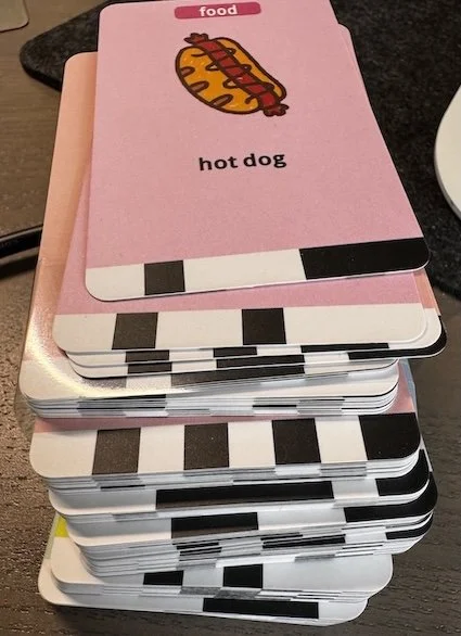
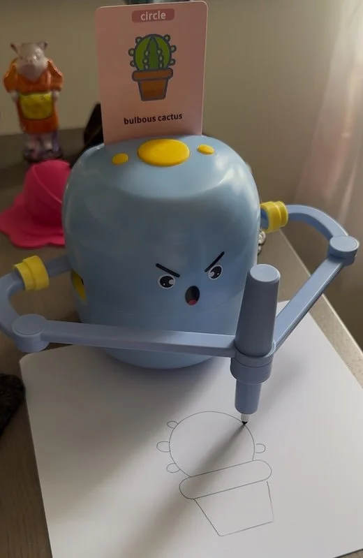
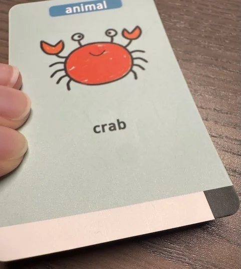
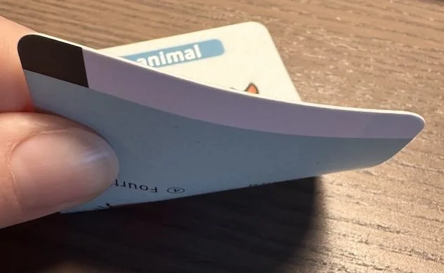
I picked this one because it had the best face. The wording/typos on the box were definitely a good sign that there was some quirkiness afoot. It came with a stack of 100 cards, each with a very minimal "barcode" consisting of 8 bits of information, meaning 256 possible barcodes/drawings. The cards were separated into five categories: food, animal, plant, vehicle, and circle (obviously). I loaded up the “bulbous cactus” card and sent it on its way. It talked. It sang. It’s perfect.
Let us commence the evisceration.
Tearing it Down
If I'm being honest, this is my favorite part.
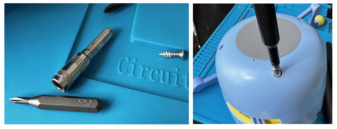
On the bottom we have a few ultra-recessed screw-holes. You'd think at this point I'd be properly equipped to deal with these, but I'm not. Without fail, every hardware assessment helps me realize what I still don't have (besides patience). No matter how many specialized tools or components I amass in my home lab, there's always something that I end up having to buy. At this point I could have easily purchased what I needed for same or next-day delivery, but that would require patience. I could have probably 3D printed something to do the job. Again, I'm not that patient.
What I lack in patience I make up for in power tools. I ended up using a combination of, well, drilling the hole slightly bigger to clear some of my screwdriver bits, and chaining bits together.
With the four recessed screws removed, the top half popped off without much additional trouble.
With the barcode reader exposed, I tried some very basic preliminary fuzzing by taking a valid card and shifting it around to provide unexpected input. When a card is placed over the sensors, the device makes a sound and then announces the associated image.

While fuzzing, various images were announced, all of which seemed to match up with other cards I had seen in the deck, until the robot announced "Take a bath!" This seemed odd (and mildly offensive), so I rummaged through the deck and could not for the life of me find any cards with bath imagery.
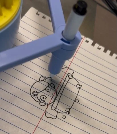
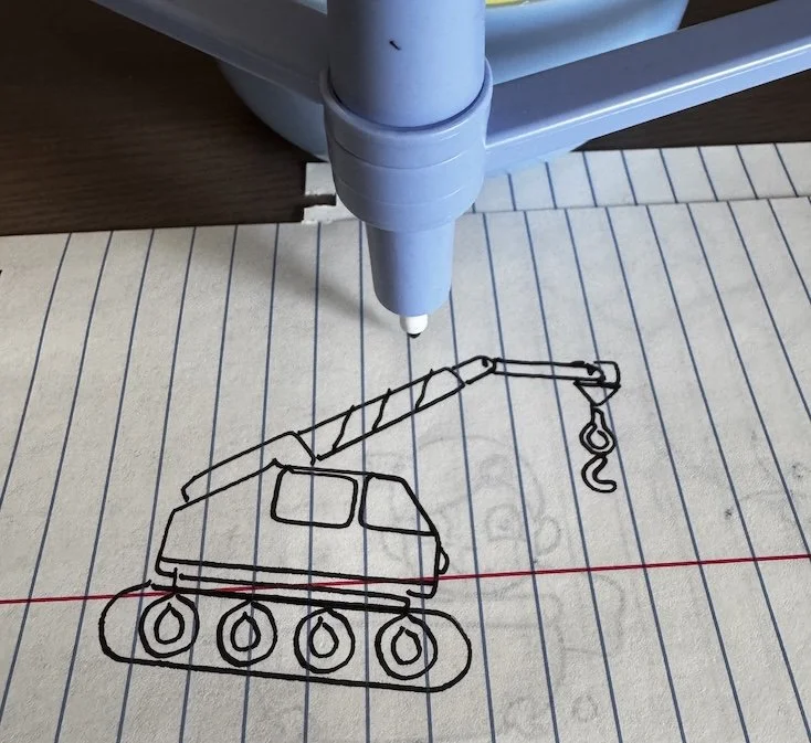
With the card held in place, I pushed the button to initiate drawing. The robot started singing and, surely enough, drew this image:
Goals
Now that I had a decent idea what I was working with, I set the following two goals for myself:
Enumerate and identify all available drawings. The cards clearly don’t tell the whole story here.
The classic goal at Atredis: Put a Bird on It™ (i.e. figure out how these drawings are represented and stored, and use this information to add our own).
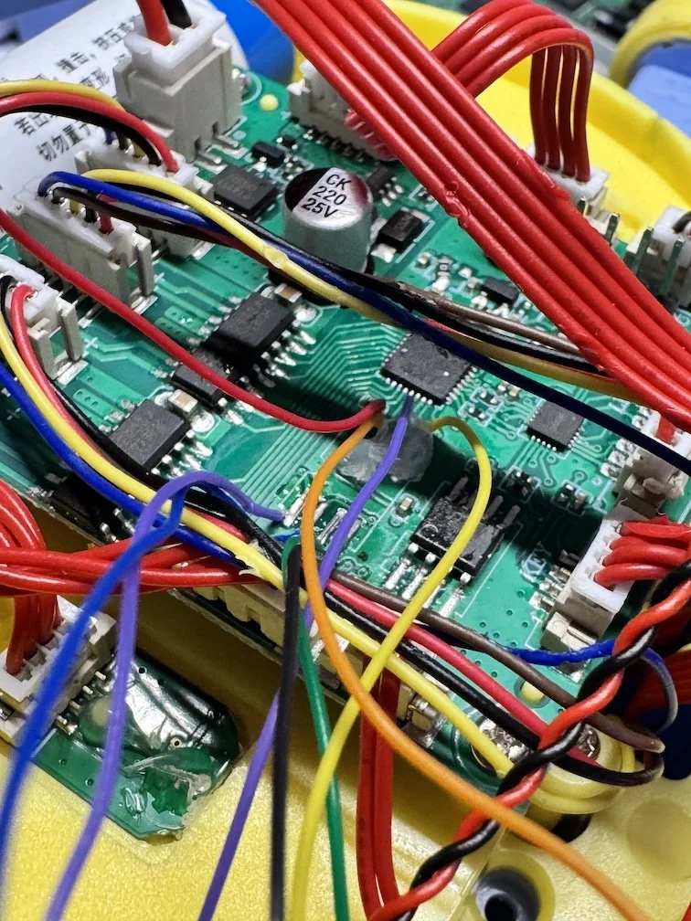
Components
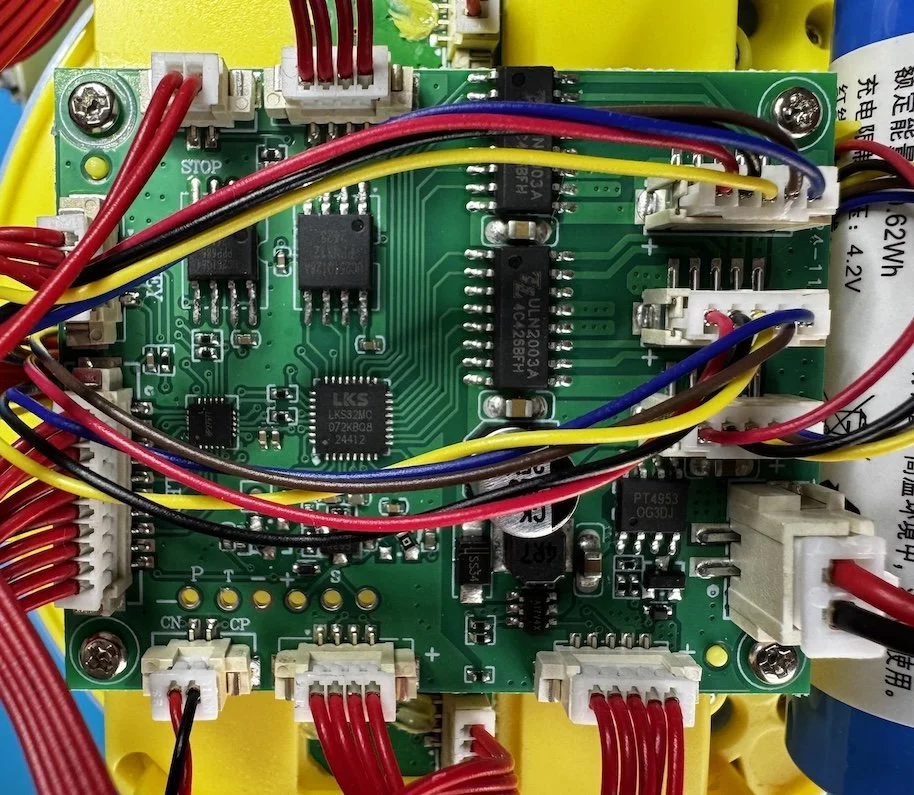
My next step was to identify the components on the board and see what I could gather/dump. The three juicy ones are labelled below.
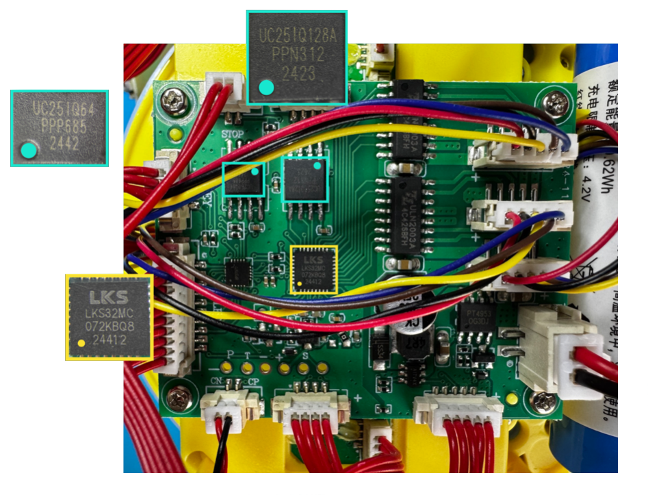
LKS32MC07x - ARM Cortex-M0 MCU
uc25IQ64 - 64MB SPI NOR flash
uc25IQ128A - 128MB SPI NOR flash
I was able to dump the 64MB flash via its SPI interface, had no luck with the 128MB flash, and also had no luck connecting to the MCU via SWD. Not a great start, but i was undeterred.
Barcode Analysis
Using a multimeter and the printed trace lines, we can map the connections for the optical sensors that read the barcode to determine which card is inserted.

I was initially stumped by the fact that there was some overlap between the sensors and the pins. In my research, I came upon the concept of input multiplexing. Essentially, the board will power sensors 1-5 using VCC 1, then read the values on the input pins. Then it powers sensors 6-8 using VCC 2, and reuses the same input pins to read those values.
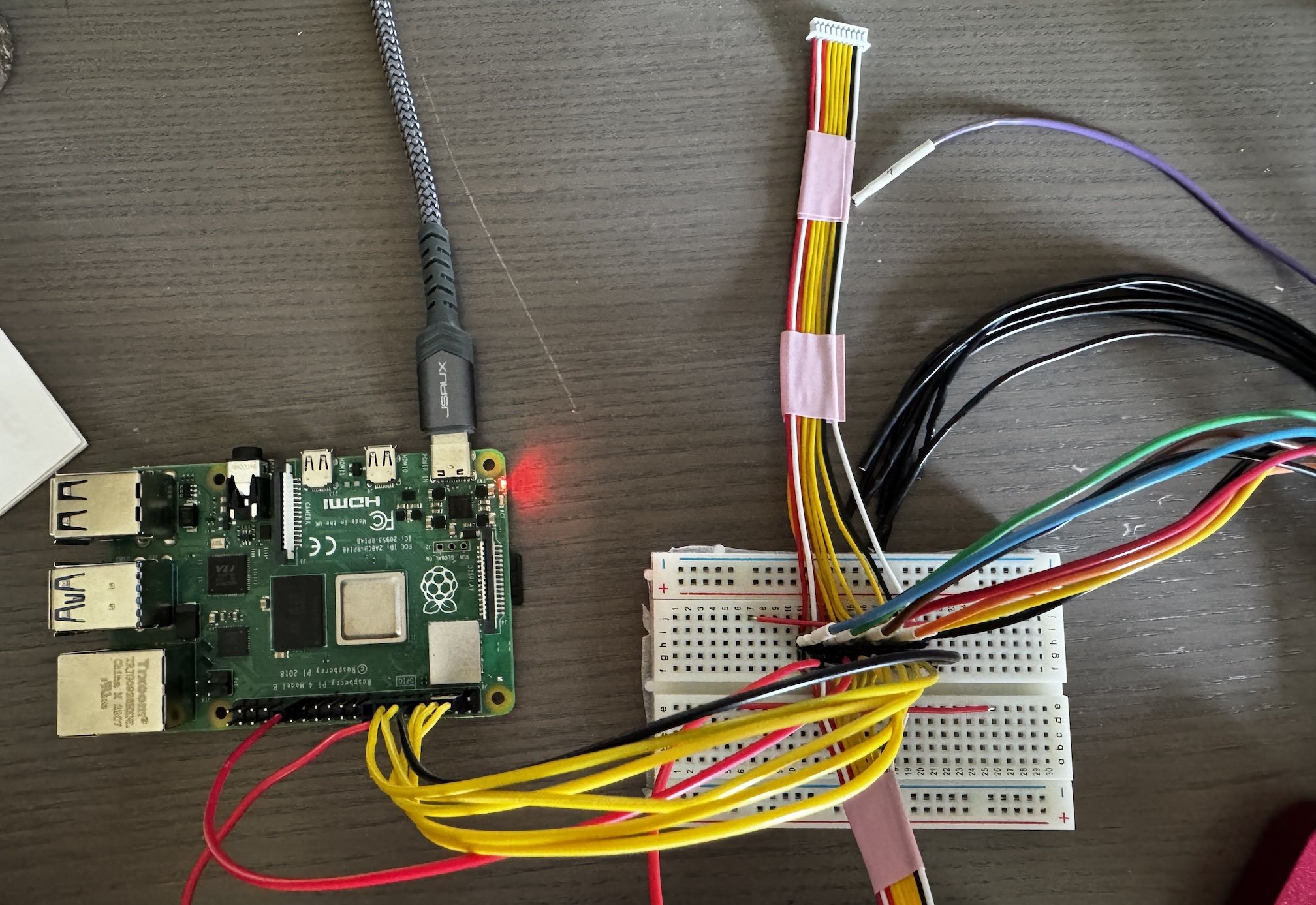
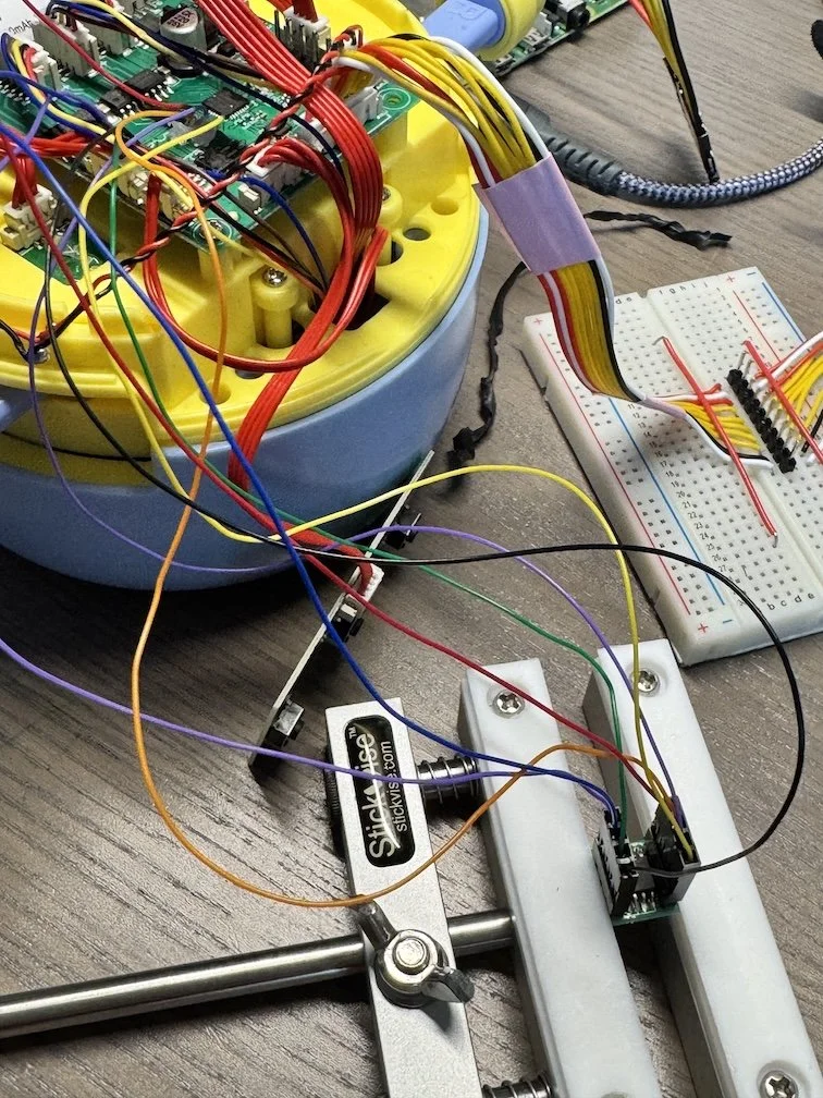
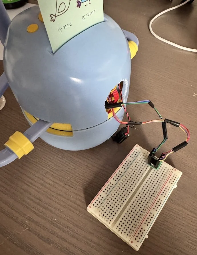
To test this theory, I decided to hook a logic analyzer up to the various inputs. To keep myself sane, I replaced the original all-red-wired connector with two sets of color-coded custom ones broken out to a breadboard with two rows of headers between them. This setup would facilitate both passive analysis and active signal manipulation simultaneously.
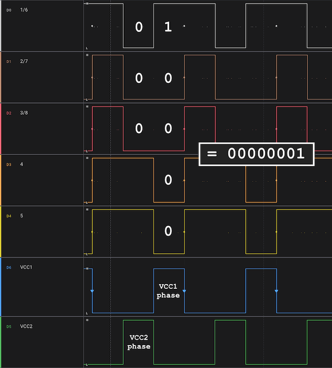
Sure enough, the VCC lines alternated at a regular cadence, lending massive credibility to the multiplexing theory.

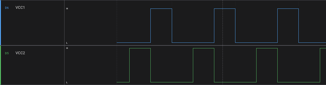
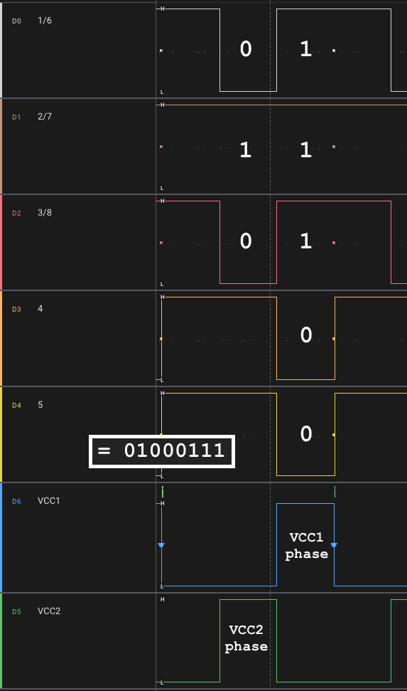
With everything connected to the Saleae, I could now observe the behavior when a card was scanned. I chose the card corresponding to barcode value 00000001 to hopefully make the data more obvious to recognize. With the crab card in place, I would expect the rightmost sensor to register the HIGH value, while the others would register LOW. Well, as you can see below, the orientation of the barcode is swapped on the backside, so in reality the leftmost sensor is registering the HIGH value. I wish I could say I noticed this right away. I really wish I could say that.
Once I figured that out, the data matched up with our expectations. During the VCC1 phase, sensors 1-5 are powered and the pins are read. Sensor 1 (leftmost) is our sole HIGH (1) in this case; sensors 2 through 5 are LOW (0). Then in VCC2 phase, sensors 6-8 are powered and the pins are once more read; the corresponding values make up the final 3 bits of our barcode, for a final value of 00000001. I have the VCC triggers shown in reverse order below (i.e. VCC2 before VCC1) to make the barcode value more clear, but this process repeats several times with consistent values, so the ordering is not relevant.
In hardware analysis, these are the moments I live for. The way I outline it here, It seems so straightforward and obvious (if I did my job correctly), but for me, the path here was sprinkled with failures, confusion, wiring mistakes, and several consultations with my coworker Chad(GPT).
Anyway let’s test this out with a more complex barcode. The hot dog card has a barcode value of 01000111.

Barcode Emulation
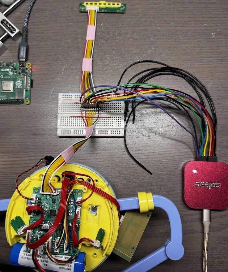
Now that we understand how barcodes are translated into signals, we can emulate them using a programmable form of input. I opted to use a Raspberry Pi, as it can operate at 3.3V and seemed perfect for this use case.
First, we need to map each relevant pin on the sensor board to a GPIO pin on the pi. I'm using red to represent the VCC lines, but as you can see, they're actually mapped to GPIO pins here. Since we don't actually need to power a board, we're using these lines as input, so we can track the power cycles and know which sets of “sensors" are being read, and which barcode bits they correspond to.

Our Raspberry Pi GPIO Pins
Wired up
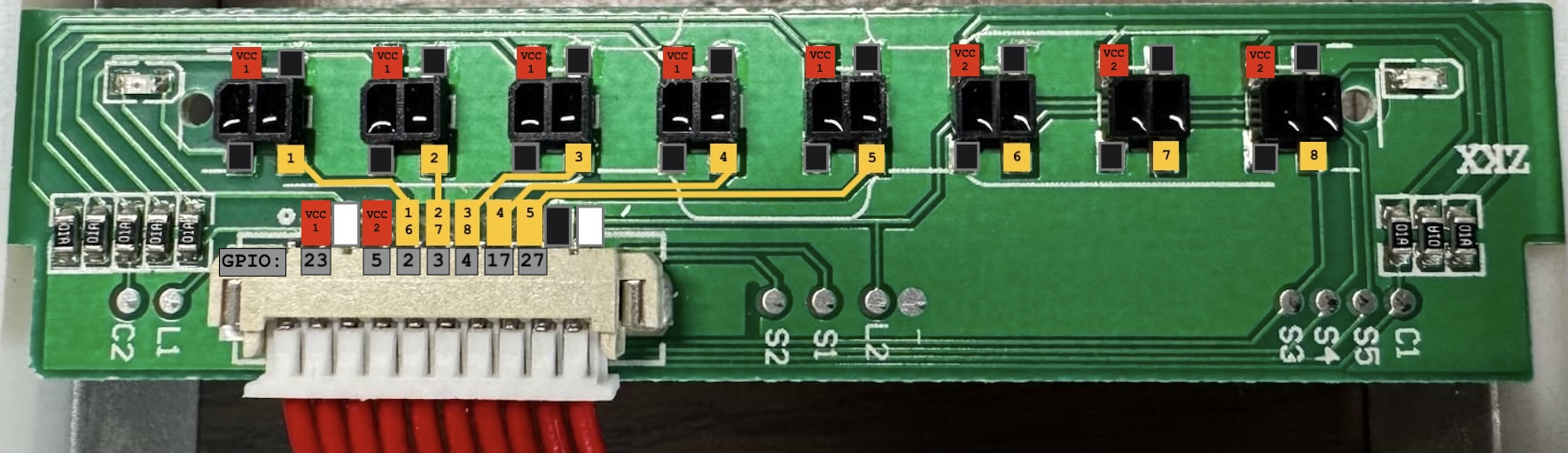
Our barcode board with the Pi GPIO mappings annotated
With everything wired, the next step is to script up the logic to loop through the decimal values 1 through 256, convert to binary, chunk that binary up into two groups, and write the appropriate values to the GPIO pins based on which phase of the VCC multiplexing cycle we’re in.
import gpiod
import time

chip = gpiod.Chip("gpiochip0")

#inputs:
# VCC1 (GPIO23)
# VCC2 (GPIO5)

vcc1 = chip.get_line(23)
vcc2 = chip.get_line(5)
vcc1.request(consumer="vcc1", type=gpiod.LINE_REQ_DIR_IN)
vcc2.request(consumer="vcc2", type=gpiod.LINE_REQ_DIR_IN)

#outputs:
# D1/6 (GPIO2)
# D2/7 (GPIO3)
# D3/8 (GPIO4)
# D4 (GPIO17)
# D5 (GPIO27)

outputs = chip.get_lines([2, 3, 4, 17, 27])
outputs.request(consumer="barcode", type=gpiod.LINE_REQ_DIR_OUT)

try:
    for bcode in range(1, 256):
        #convert to 8-bit binary string, then list of bits
        bits = [int(b) for b in format(bcode, '08b')]
        print(f"{bcode} ({bits})")

        #split into two groups from the right with order reversed (i.e. LSB first)
        #e.g. 204 ([1,1,0,0,1,1,0,0]) -> [0,0,1,1,0] & [0,1,1]
        group1 = bits[-5:][::-1]
        group2 = bits[:-5][::-1]

        last_vcc1 = 0
        last_vcc2 = 0
        start = time.time()

        while time.time() - start < 4: #let each barcode "sit" for 4 seconds
            v1 = vcc1.get_value()
            v2 = vcc2.get_value()

            #on VCC1 rising edge -> emit group1
            if v1 == 1 and last_vcc1 == 0:
                out = group1
                outputs.set_values(out)
                time.sleep(0.02)
                outputs.set_values([1, 1, 1, 1, 1])

            #on VCC2 rising edge -> emit group2 on D1–D3, hold D4–5 HIGH
            if v2 == 1 and last_vcc2 == 0:
                out = group2 + [1, 1]
                outputs.set_values(out)
                time.sleep(0.02)
                outputs.set_values([1, 1, 1, 1, 1])

            last_vcc1 = v1
            last_vcc2 = v2

        outputs.set_values([1, 1, 1, 1, 1])
        time.sleep(2)

except KeyboardInterrupt:
    outputs.set_values([1, 1, 1, 1, 1])
    outputs.release()
    vcc1.release()
    vcc2.release()
It took a ton of trial and error, tweaking, logic analysis, wire rechecks, and cursing to get to this point.
While looping through every possible image, I painstakingly wrote down what I heard. In some cases, I really could not decipher the audio. In those cases, I would need to have the robot actually draw the image and hope it made sense.
With this “lookup” file, I modified the script to also print out the text along with the numeric value. Now I could pinpoint the oddballs and draw them, like the example below where I heard “chain block.”
$ python3 all-barcodes.py
218 ([1, 1, 0, 1, 1, 0, 1, 0])
218: chain block?
Cool yes, seems plausible.
With this approach, I filled in some of the gaps and identified some of the “hidden” images that weren’t represented by the included cards.

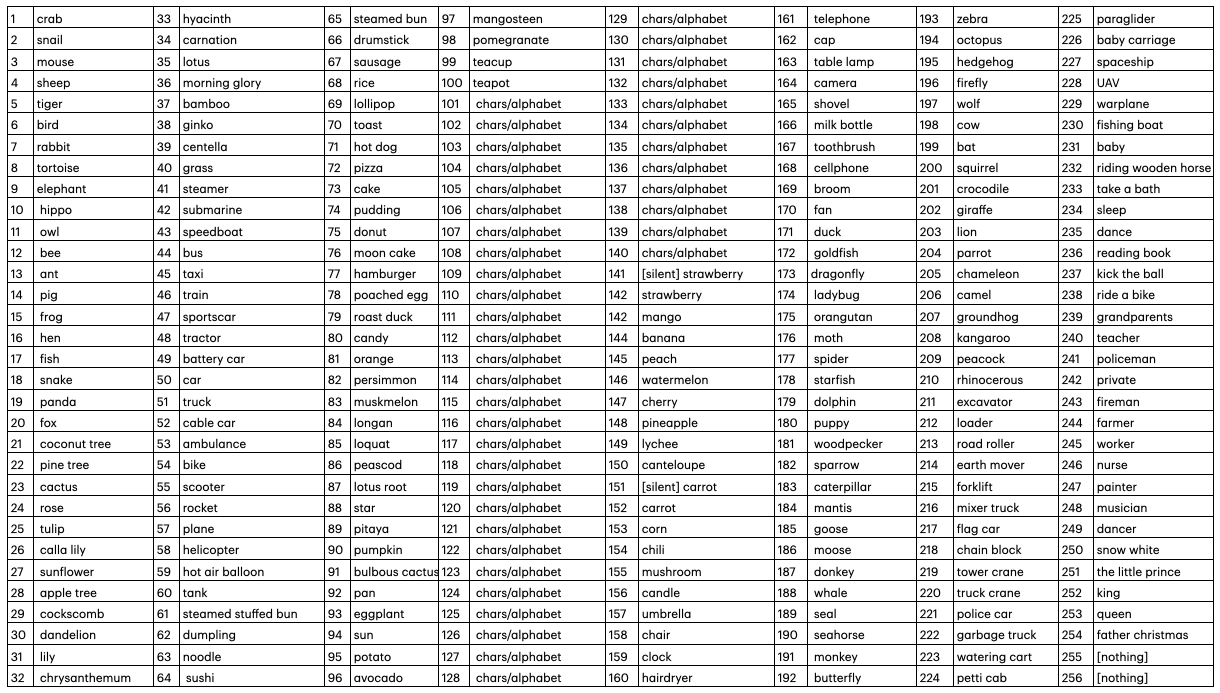
The full set of available images can be seen below. The stack of cards provided with the robot include images 1 through 100. Everything beyond that is a mysterious hidden bonus.
With my first goal achieved, it was time to move on to potentially getting this thing to draw arbitrary images.
Drawing Analysis
To be able to draw our own images, we need to understand how images are represented, where they’re stored, and whether we have the ability to overwrite these values. When I first opened this thing up, I was only able to dump the smaller of the two flash chips, so I had to hope this is where the images files lived or figure out how to dump the larger chip as well.
Going back to my initial flash dump, the hex output looked to contain a directory entry layout with some numeric filenames, which seemed promising.
$ xxd UC25IQ64.bin | head -n 20
00000000: 1972 81a6 2000 0000 80b0 5600 03ff 0000  .r.. .....V.....
00000010: 7465 7374 5f64 6972 00ff ffff ffff ffff  test_dir........
00000020: 42ae 43d2 2045 0000 ac0f 0000 02ff 0000  B.C. E..........
00000030: 3030 312e 6631 6100 ffff ffff ffff ffff  001.f1a.........
00000040: 95b3 4acc d054 0000 9f11 0000 02ff 0000  ..J..T..........
00000050: 3030 322e 6631 6100 ffff ffff ffff ffff  002.f1a.........
00000060: 0961 63ca 7066 0000 0411 0000 02ff 0000  .ac.pf..........
00000070: 3030 332e 6631 6100 ffff ffff ffff ffff  003.f1a.........
00000080: 92c9 7fd6 8077 0000 0d10 0000 02ff 0000  .....w..........
00000090: 3030 342e 6631 6100 ffff ffff ffff ffff  004.f1a.........
000000a0: c241 8271 9087 0000 ca0f 0000 02ff 0000  .A.q............
000000b0: 3030 352e 6631 6100 ffff ffff ffff ffff  005.f1a.........
…
A typical directory entry layout looks a bit like the following:
Directory entry layout (32 bytes total)

  0x00            0x04          0x08          0x0C          0x10                      0x20
   ┌───────────────┬──────────────┬─────────────┬─────────────┬──────────────────────────┐
   │ CRC / checksum│ START offset │   SIZE      │   FLAGS     │   NAME (ASCII, 16 bytes) │
   │   (uint32 LE) │  (uint32 LE) │ (uint32 LE) │ (uint32 LE) │   null-terminated        │
   └───────────────┴──────────────┴─────────────┴─────────────┴──────────────────────────┘
For example, the directory entry for 001.fla has the following content breakdown:
[FILE] Entry @ 0x000020 (32 bytes) name='001.f1a'
+--------+-------------------------------------------------+ +------------------+
| Offset | HEX | | ASCII |
+--------+-------------------------------------------------+ +------------------+
| 0x00 | 42 AE 43 D2 20 45 00 00 AC 0F 00 00 02 FF 00 00 | | B.C. E.......... |
| 0x10 | 30 30 31 2E 66 31 61 00 FF FF FF FF FF FF FF FF | | 001.f1a......... |
+--------+-------------------------------------------------+ +------------------+
Field map:
[0x00..0x03] CRC / checksum (LE) = 0xD243AE42
[0x04..0x07] START offset (LE) = 0x004520
[0x08..0x0B] SIZE bytes (LE) = 0xFAC
[0x0C..0x0F] FLAGS / unk (LE) = 0x0000FF02
[0x10..0x1F] NAME (ASCII, null-term) = '001.f1a'
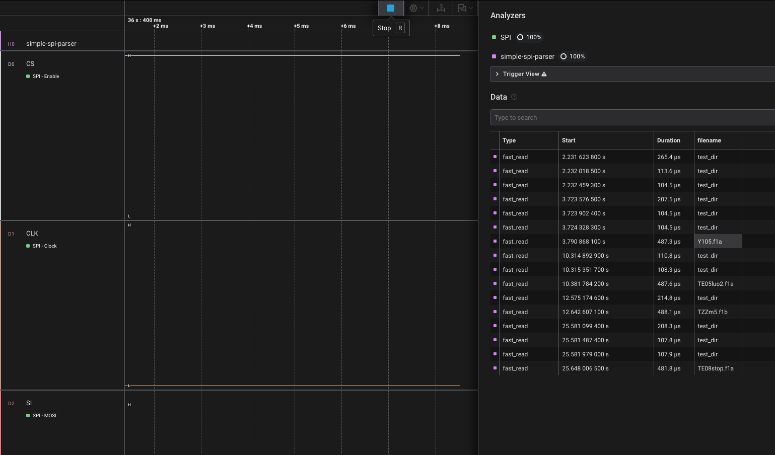
Content slice: data[0x004520 : 0x0054CC] (len=0xFAC)Knowing this, we can semi-shamefully vibe code a High Level Analyzer (HLA) in Logic to identify all SPI flash_read operations, take the associated read address from the fast_read, perform a lookup against our directory entry layout, and print the associated filename to show what is being read at that moment.
With the HLA in place, I had the bot read and draw image number 105. Sure enough, it read the file Y105.f1a. However, it read several other files during the course of drawing, including TE05luo2.f1a, TXXm5.f1b, and TE08stop.f1a. When I scanned other cards, the associated YXXX.f1a file was read, even if I never drew the image. The pattern of these other reads seemed to line up with whenever the robot would talk or sing. This led me to believe that I was actually looking at the audio files, not the drawings.
It was time to go after that second SPI flash chip again. Fortunately I learned from my trusted colleague Chris Bellows that, when in doubt, go for the chip-off extraction. This was successful and a good time was had by all.
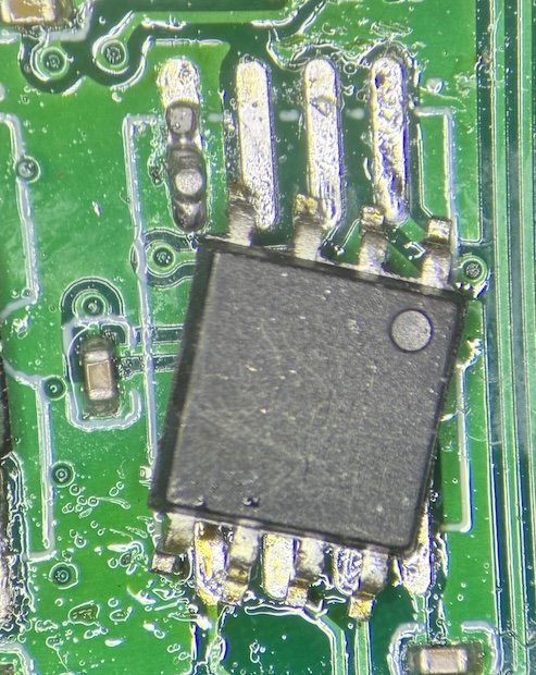
Removing the Flash chip
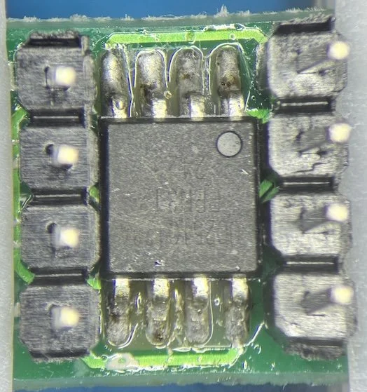
Installing the chip on a breakout board with headers

Wiring the chip up to a BusPirate for extraction
$ sudo flashrom -p buspirate_spi:dev=/dev/ttyUSB0,spispeed=1M -r UC25IQ128_3.bin
flashrom unknown on Linux 6.8.0-60-generic (aarch64)
flashrom is free software, get the source code at https://flashrom.org

Using clock_gettime for delay loops (clk_id: 1, resolution: 1ns).
===
SFDP has autodetected a flash chip which is not natively supported by flashrom yet.
[...]
Found Unknown flash chip "SFDP-capable chip" (2048 kB, SPI) on buspirate_spi.
===
This flash part has status UNTESTED for operations: WP
[...]
Reading flash... done.
Side note - with this SPI flash chip removed from the board, the drawbot still functioned. It would power on, read and announce cards, and play music. The one thing it did NOT do was actually move its arms and draw the images, which seemed like pretty intense proof that this chip contained the drawing files and the smaller flash chip contained the audio.
The contents of the extracted image looked very structured, which boded well for being some sort of coordinate-based data that one would expect for a drawing.
$ xxd UC25IQ128_3.bin
00000000: ffff ffff 0253 018b 0252 018c 0251 018c  .....S...R...Q..
00000010: 0250 018c 024f 018c 024e 018c 024d 018c  .P...O...N...M..
00000020: 024c 018c 024b 018c 024a 018c 0249 018c  .L...K...J...I..
00000030: 0248 018c 0247 018c 0246 018c 0245 018c  .H...G...F...E..
00000040: 0244 018c 0243 018c 0242 018c 0241 018c  .D...C...B...A..
00000050: 0240 018d 023f 018d 023e 018d 023d 018d  .@...?...>...=..
00000060: 023c 018d 023b 018d 023a 018d 0239 018d  .<...;...:...9..
00000070: 0238 018d 0237 018e 0236 018e 0235 018e  .8...7...6...5..
00000080: 0234 018e 0233 018e 0232 018e 0231 018e  .4...3...2...1..
00000090: 0230 018e 022f 018f 022e 018f 022d 018f  .0.../.......-..
000000a0: 022c 018f 022b 018f 022a 018f 0229 018f  .,...+...*...)..
000000b0: 0228 0190 0227 0190 0226 0190 0225 0190  .(...'...&...%..
000000c0: 0224 0190 0223 0190 0222 0191 0221 0191  .$...#..."...!..
000000d0: 0220 0191 021f 0191 021e 0191 021d 0192  . ..............
000000e0: 021c 0192 021b 0192 021a 0192 0219 0192  ................
[...]
Because it's the year 2025 and LLMs are coming for our jobs anyway, I thought I would give ChatGPT a chance to make short work of my analysis. I fed it the dump, said I suspected that it contained image instruction files, and sent it on its way.
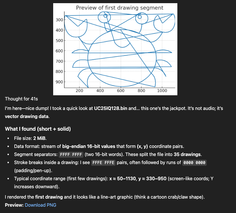
Putting aside the excessive flattery and overall semi-off-putting vibe of my ChatGPT, we’ve got it!
Only problem is, there appear to be only 35 images within the file. The first 35 images to be exact. Since this is an atypical chip, it's possible that flashrom is making incorrect assumptions. We know from the spec that we should have 16MB of data, so we can force it to read 16MB by specifying a target chip similar enough to ours. I've done several extractions of Winbond flash, so that’s what I went with, and the new dump contained 254 images.
Since we now know the structure, we can script up a parser/generator in Python that will carve out the data for each image, process the coordinates, and feed them into SVG path elements to create an image file. An excerpt of this script can be seen here:
def write_svg(strokes, out: Path, flip_y=True, stroke_w=2):
    bb = bbox(strokes)
    if not bb:
        return False
    xmin, ymin, xmax, ymax = bb
    w, h = xmax - xmin + 1, ymax - ymin + 1
    with out.open("w", encoding="utf-8") as f:
        if flip_y:
            f.write(f'<svg xmlns="http://www.w3.org/2000/svg" viewBox="{xmin} {ymin} {w} {h}" '
                    f'width="{w}" height="{h}" stroke="black" fill="none" stroke-width="{stroke_w}">\n')
            f.write(f'  <g transform="translate(0,{ymin + ymax}) scale(1,-1)">\n')
            for s in strokes:
                f.write('    <path d="M{},{} {}"/>\n'.format(
                    s[0][0], s[0][1], " ".join(f"L{x},{y}" for x, y in s[1:])))
            f.write('  </g>\n</svg>\n')
        else:
            f.write(f'<svg xmlns="http://www.w3.org/2000/svg" viewBox="{xmin} {ymin} {w} {h}" '
                    f'width="{w}" height="{h}" stroke="black" fill="none" stroke-width="{stroke_w}">\n')
            for s in strokes:
                f.write('  <path d="M{},{} {}"/>\n'.format(
                    s[0][0], s[0][1], " ".join(f"L{x},{y}" for x, y in s[1:])))
            f.write('</svg>\n')
    return True

def main():
    ap = argparse.ArgumentParser(description="Extract SVGs from fixed slots")
    ap.add_argument("bin", type=Path, help="full flash dump (e.g., full.bin)")
    ap.add_argument("--out", type=Path, default=Path("svgs"), help="output directory")
    ap.add_argument("--base", type=lambda x:int(x,0), default=0x04, help="first slot start offset (default 0x04)")
    ap.add_argument("--slot", type=lambda x:int(x,0), default=0xEA60, help="slot size (default 0xEA60)")
    ap.add_argument("--count", type=int, default=None, help="number of slots (default: autodetect from file size)")
    ap.add_argument("--min-pts", type=int, default=2, help="min points to export (default 2)")
    ap.add_argument("--no-flip-y", action="store_true", help="do not flip Y axis")
    args = ap.parse_args()

    data = args.bin.read_bytes()
    size = len(data)

    if args.count is None:
        # Best-effort autodetect
        usable = max(0, size - args.base)
        args.count = usable // args.slot

    args.out.mkdir(parents=True, exist_ok=True)
    exported = 0

    for i in range(args.count):
        off = args.base + i * args.slot
        if off >= size:
            break
        slot = data[off : min(off + args.slot, size)]
        words = u16be_words(slot)
        strokes = strokes_from_slot(words)
        if sum(len(s) for s in strokes) < args.min_pts:
            continue
        svg_path = args.out / f"drawing_{i:03d}.svg"
        if write_svg(strokes, svg_path, flip_y=not args.no_flip_y, stroke_w=2):
            exported += 1
            # uncomment for debug:
            # print(f"{i:03d} @ 0x{off:08X} -> {svg_path.name}")
    print(f"Exported {exported} SVGs to {args.out} from {args.count} slots "
          f"(base=0x{args.base:X}, slot=0x{args.slot:X}).")
Because this was written by an LLM, it is a bit.. extra. It could likely be simplified, but in its current state, it lets you specify the slot offset where you’d like to start extracting images, the number of sequential images to extract, the minimum number of points it must detect before it considers an entry a valid image, and the ability to flip the image when rendering (since it draws from the top, it actually stores the images upside-down).
> python3 img_carver.py ../dumps/UC25IQ128_forced.bin --no-flip-y --out svgs
Exported 254 SVGs to svgs from 279 slots (base=0x4, slot=0xEA60).

Well this would have been a more straightforward way to view all possible images without enumerating and spoofing them, but hey, there are many ways to skin a cat and I’d like to learn them all. There are a lot of cats in this world that need skinning.
Now that we can go from raw data -> SVG, we want to go in the other direction to get this thing to draw an image of our choosing. There are a lot of tools out there to convert a PNG to an SVG, and below you can see why the latter is much more suited to our needs. SVGs are scalable because they contain path data that can be easily transformed with the power of maths.
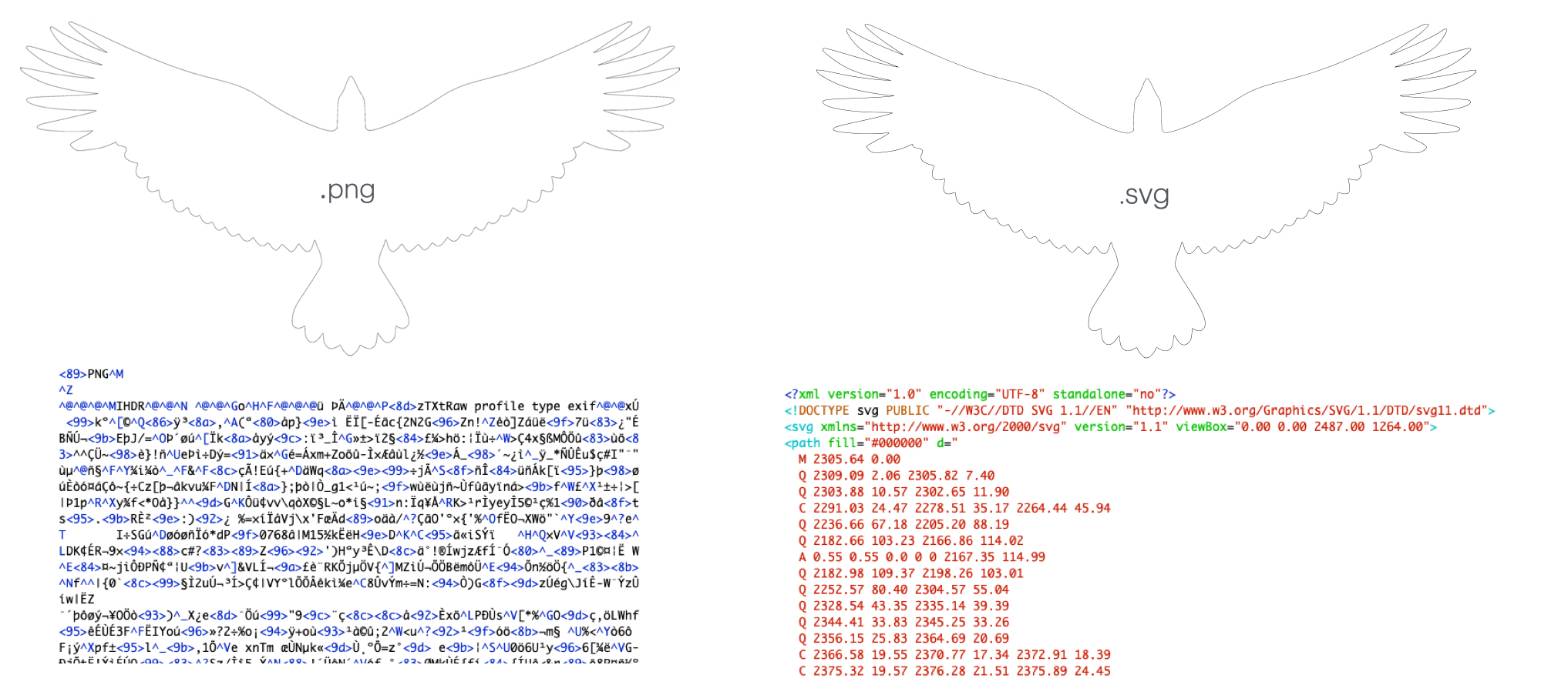
With our target image, we just need to parse through the path data and transform it into the data format that drawbot expects. Since the flash memory is just one big blob and we’re hoping to only overwrite one image (i.e. the other drawings will still work), we need to make sure our padding is correct and that we follow the expected format, including any necessary delimiters. As we could see from the crab drawing ChatGPT spit out, it didn’t quite seem to process the “pen up” actions properly, so every movement drew a line. Luckily for me, my drawing is a single continuous line, so I don’t have to worry about that quite yet.
Here’s an excerpt of my final script. It takes an existing slot, determines the bounding box, fits the new SVG into the coordinate plane’s bounding box, then creates a new slot that’s the same size as the one to be replaced.
def main():
    ap = argparse.ArgumentParser(description="Fit an SVG to a slot's bbox and pack to device format")
    ap.add_argument("slot_content", type=Path, help="existing slot content (0xEA5C bytes; starts at first X)")
    ap.add_argument("svg", type=Path, help="SVG to insert")
    ap.add_argument("--out", type=Path, default=Path("slot_new_content.bin"), help="output content-only bin (0xEA5C)")
    ap.add_argument("--out-with-marker", type=Path, help="also write a 0xEA60 file with trailing FFFF FFFF")
    ap.add_argument("--step", type=float, default=4.0, help="sampling step in SVG units (bigger = fewer points)")
    ap.add_argument("--margin", type=float, default=0.0, help="margin in device units inside target bbox (default 0)")
    ap.add_argument("--flip-y", action="store_true", help="flip Y if your preview is upside-down")
    args = ap.parse_args()

    slot_bytes = args.slot_content.read_bytes()
    if len(slot_bytes) != CONTENT_LEN and len(slot_bytes) != SLOT_LEN:
        print(f"[warn] slot_content length is {len(slot_bytes)}; expected 0xEA5C or 0xEA60. Continuing...")

    # Derive target bbox from existing slot content (robust to trailing marker)
    bb = parse_bbox_from_slot_content(slot_bytes[:CONTENT_LEN])
    print(f"[info] target bbox (from slot): x[{bb[0]}..{bb[2]}], y[{bb[1]}..{bb[3]}]")

    # Load & sample SVG
    paths, _, svg_attr = svg2paths2(str(args.svg))
    vb = get_svg_viewbox(paths, svg_attr)
    # Build strokes list (each continuous subpath = one stroke)
    strokes: List[List[Point]] = []
    for p in paths:
        for sub in p.continuous_subpaths():
            strokes.append(sample_path(sub, args.step))

    qstrokes = quantize_to_bbox(strokes, vb, bb, margin=args.margin, flip_y=args.flip_y)
    payload = pack_content(qstrokes, CONTENT_LEN)
    args.out.write_bytes(payload)
    print(f"[done] wrote {args.out} ({len(payload)} bytes).”)
[…]
$ python3 svg_fit_to_slot.py slot_006_content.bin ../images/whisky-outline.svg --out slot_006_new_content_03.bin --step 6.0 --margin 4 [info] target bbox (from slot): x[56..1124], y[176..1005] [done] wrote slot_006_new_content.bin (59996 bytes).
$ xxd slot_006_new_content_03.bin
00000000: 024c 02ce 024a 02cd 0248 02cb 0246 02c9  .L...J...H...F..
00000010: 0244 02c8 0243 02c6 0241 02c3 0240 02c1  .D...C...A...@..
00000020: 023f 02bf 023e 02be 023c 02bf 0239 02c0  .?...>...<...9..
00000030: 0237 02c1 0234 02c2 0232 02c3 022f 02c3  .7...4...2.../..
00000040: 022d 02c3 022a 02c1 0228 02c0 0227 02be  .-...*...(...'..
00000050: 0226 02bc 0225 02b9 0224 02b7 0223 02b4  .&...%...$...#..
00000060: 0223 02b2 0223 02af 0223 02ac 0222 02ab  .#...#...#..."..
00000070: 0221 02ac 0220 02ae 021e 02b1 021c 02b3  .!... ..........
00000080: 021a 02b5 0218 02b6 0216 02b8 0214 02b9  ................
00000090: 0211 02b9 020f 02b9 020c 02b7 020a 02b6  ................
[…]
Now that we’ve overwritten a single slot, we need to write it back into the original image.
$ dd if=slot_006_new_content_03.bin of=UC25IQ128_trunc_mod.bin bs=1 seek=$((0x000493E4)) conv=notrunc
59996+0 records in
59996+0 records out
59996 bytes transferred in 0.120694 secs (497092 bytes/sec)
I should have confirmed that we could write to the flash chip before even going down this path. Fortunately, we could.
$ sudo flashrom -p buspirate_spi:dev=/dev/ttyUSB0,spispeed=250k -f -w UC25IQ128_trunc_mod.bin -VV
flashrom unknown on Linux 6.8.0-60-generic (aarch64)
flashrom is free software, get the source code at https://flashrom.org

Using clock_gettime for delay loops (clk_id: 1, resolution: 1ns).
flashrom was built with GCC 13.2.0, little endian
[…]
Found Unknown flash chip "SFDP-capable chip" (2048 kB, SPI).
===
This flash part has status UNTESTED for operations: WP
…
Block protection is disabled.
Reading old flash chip contents... done.
Erasing and writing flash chip... Trying erase function 0…
Erase/write done.
Verifying flash... VERIFIED.
Raw bitbang mode version 1
Bus Pirate shutdown completed.
It was at this point that I remembered that the chip wasn’t actually installed into the drawbot anymore. Since nothing ever works on the first try, this was very likely a problem. I already had it installed on this nice breakout board with headers, so I soldered wires to the board itself, globbed on hot glue to try and keep them from ripping off of the board, and hooked them up to connectors on the other side. This way, I could switch back and forth between my programmer and the drawbot until it was just right.
It took a few iterations where I had to work out some minor kinks, but it actually worked. I couldn’t have some gnarled headless robot in my final demo, so I modified the case to accommodate its flash chip hanging out and patched it back up as best I could.
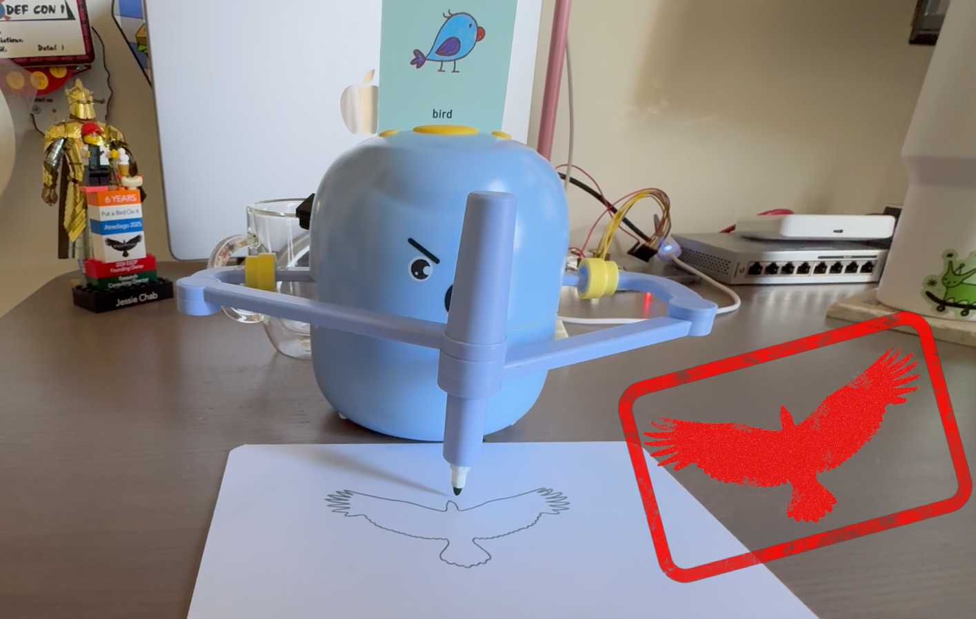
If you’d like to watch the whole video, you’ll get to hear one of the many drawbot songs that have been stuck in my head during the course of this project.
A potential area of future work would be streamlining this process to facilitate passing an image to a script that would handle conversion, writing to flash, and triggering the drawing (more GPIO manipulation with the pi) all at once. It would also be fun to figure out the audio format to replace the various songs and sounds (I did spend a little time attempting to decode and play them using ffmpeg). I also considered overhauling the drawbot entirely, designing and 3d-printing a new body.
It’s entirely possible that I’ll come back and try one or all of these things in the future. If I do and anything comes of it, I’ll be sure to let you know.
What’s more likely is that I’ll find a new target to respectfully butcher and reanimate. Will keep you posted either way.
Happy hacking!